When using the Motorola GM300 to GM950 series radios as gateway node hotspots for MMDVM, Echolink, and IRLP, I found it necessary to adapt the accessory socket at the rear of the radio to a standard 6 pin mini-DIN socket. The wiring diagram and picture are as follows and the parts used are simply a old 12 socket IDC female modified to connect to the middle of the existing 16 pin male socket with pins 1,2,15,16 not connected. All housed in a small Hammond case.
Monday, January 11, 2021
Monday, January 4, 2021
Little Tarheel screwdriver antenna limit alarm
The Little Tarheel screwdriver antenna is normally supplied with a manual rocker switch controlling motor drive direction with instructions not to exceed travel limit for more than ten seconds thus avoiding drive motor burn out. The third party controllers recommended by Tarheel the are very expensive so here is a limit alarm circuit that I obtained from K0BG.com's website; its really simple, just one transistor, one LED, two resistors and a fuse. An optional buzzer can also be added in parallel with LED if required. The manual switch is incorporated in the case as shown in photo and circuit diagram. When limit of travel is reached the high current is detected by the circuit and the LED illuminates,and optional buzzer will sound.
Friday, January 1, 2021
COS for Baofeng BF888
The provision of a Carrier operated squelch or COS can be useful if one is attempting to use a transceiver as a node radio in the service of Echolink, IRLP, Allstar or Wires-X analog system. COS is used to detect an FM carrier on the radio receive side of the node and lets the computer know that a RF signal has been detected so that the received signal can be routed to the system server or local controller in the case of Wires-X.
Using the Baofeng BF888, which is a very inexpensive radio ( less than $20 ) is great value anyway but when used as a node radio it's even better.This simple modification does not require any major alteration to the radio.
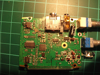
The process of implementing this feature is explained with the help of the following picture, its shows how to connect a wire to pin 1 of audio IC type BL6281 at top left hand side which is routed to a 0.1 mm single female crimp connector housing glued in between mic and speaker jack on the side of the radio.
A single solid wire maybe be feed through the rubber grommet around the mic/speaker jack and wire to the node controller interface or Wires-X HRI200 box.
When the radios squelch is activated by a received FM signal, the voltage on pin 1 of IC goes from 0 to 2.8v, this can be configured as a carrier detect in the settings of the interface unit.
Thursday, December 24, 2020
Arduino Compass with OLED display for antenna beam heading
Here is an Arduino based electronic compass with a local OLED display, the magnetometer sensor can be mounted on a radio antenna and can output antenna heading to a PC and a local OLED.
This same circuit could be incorporated into a True bearing compass if mounted in a small case with a 9 volt battery. For purposes of demonstration the photo shows an Arduino nano with digital OLED display and a GY2713 magnitometer ,which is a break out board for the HMC5883L chip set.
The circuit diagram is included along with the Arduino sketch code, which is a combination of Adafrut's OLED and magnetometer libraries as found in the Arduino IDE.
For source code please follow this link to my google documents shared folder:
Thursday, December 10, 2020
APRS switch makes any Ham radio transceiver act like a APRS tracker
tracker.
The switch has three positions as following:
Mic: has the transceiver in normal mode with speaker/mic fully functional and the APRS system does not transmit or broadcast GPS location to the APRS system.
APRS : has the transceiver in full APRS mode and GPS locations are broadcast to the APRS system
if any stations are within range. The transceiver channel needs to be programmed for the APRS
frequency 144.800 Mhz as used in Europe.
Split: The transceiver RX is programmed for any number of your favorite repeater or simplex frequencies however the TX must be programmed for the 2m 144.800 as an output to the APRS system, So this will necessitate the programming extra bank of special split channels in your radio.
In this mode the tracker is running blind, as I live in a very quiet APRS area this is not a problem for me, however in a built up area with many APRS users this may be a problem, here is a circuit diagram
Wednesday, December 9, 2020
Ryde DATV receiver in small Hammond case
Here is Raspberry Pi4 mounted on a steel plate with a BATC gpio board
on a plastic channel as supplied by B&Q. The arrangement allows for
access to the SD card by removing the front panel, and connections to the rear for access to USB
power and HDMI. A gpio extension cable is used for the gpio board.


